power flame burner wiring diagram
Combustion burner and commercial burner service information from Power Flame. Search by Model.

How To Read Furnace Wiring Diagram Youtube
Loose connections or faulty wiring.

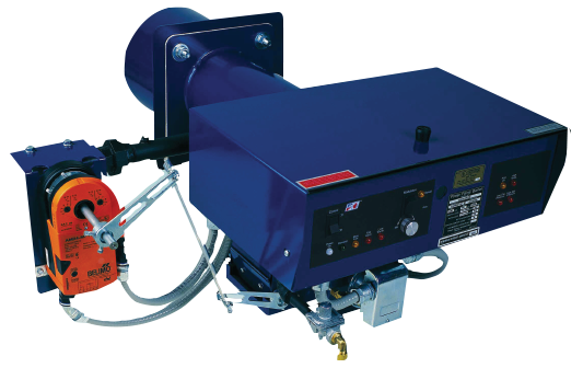
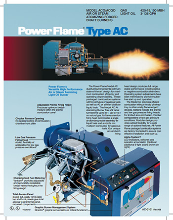
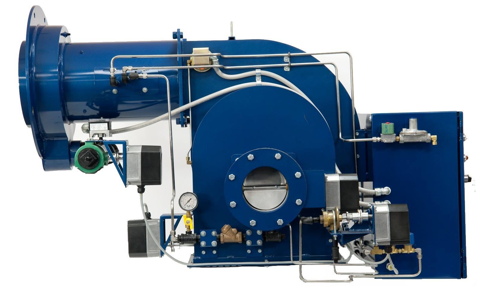
. The two power leads black and white are located inside the burner panel. Wiring and gas andor oil piping diagrams are furnished with each burner in accordance with individual job or application requirements. We manufacture a wide range of commercial burners industrial burners boiler burners.
The two power leads black and white are located inside the burner panel. Type C Burners are designed to fire a wide range of gaseous as well as 2 or similar distillate fuels. General 211 Before beginning installation carefully study these.
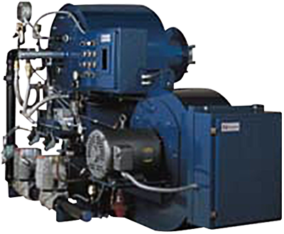
FD FDM Installation Operation Manual - POWER FLAME INCORPORATED 6 2. Cmax Manual Rev 0217 A. Each Power Flame VECTOR burner is factory test fired to ensure that components and systems are functional.
Service and replacement parts data. Figure 4 C Lr Internal Wiring Diagram End Vent Burner Manualzz. 14 Pics about Diagram together with GM HEI Ignition Module Wiring Diagram.
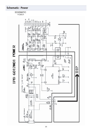
Reset and determine cause for apparent flame failure. 61 Refer to wiring diagram shipped with burner and typical wiring diagrams Figures 5 and 5A. 61 Refer to wiring diagram shipped with burner and typical wiring diagrams Figures 5 and 5A.
Product Diagrams Bill. Flame safeguard control safety switch tripped out. Wall mounted or free-standing control panels are.
Charger hp diagram hstnn ca15 circuit. Click here for the Power Flame library. Atwood Furnace Wiring Diagram.
Burner Director Management Boiler Burners Power Flame. Wiring and gas andor oil piping diagrams are furnished with each burner in accordance with individual job or application requirements. INSTALLATION 21 Burner Mounting.
62Electrical installation must be made in accordance with the NEC NFPA 70 or Canadian Electrical Code Part 1 and applicable. Wall mounted or free-standing control panels are. Tighten all terminal screws and consult.
6 WIRING 61 Refer to wiring diagram shipped with burner. On gm hei. Packaged Liquid Waste Fuel Burning systems employing the basic design.
Diagram together with GM HEI Ignition Module Wiring Diagram. Because each field application is unique the final burner set-up.
Powerflame Boilerdata Com
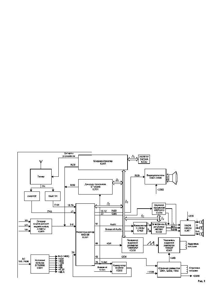
Akira Chassis 5n11 Sch Service Manual Download Schematics Eeprom Repair Info For Electronics Experts

1960 Arcoflame American Standard Oil Burner Acd Model 602 Commercial Standard Cs195 60 Heating Help The Wall

Gas Burner Primary Control Heater Service Troubleshooting

Bell Sound 2154a Power Amplifier Schematic Electronic Service Manuals
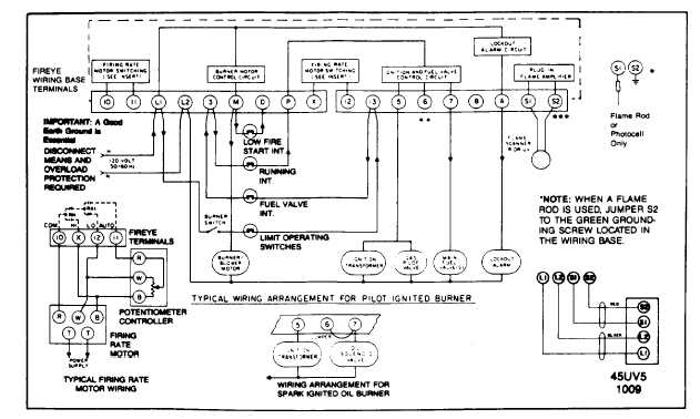
Suggested Wiring Diagram For Fireye Ep260 Ep261 Ep270 Programmer Logic

M8079 Gif
Powerflame Boilerdata Com

I Have A Burnham Boiler With A Power Flame C2 G Burner And It Will Not Start The Burner Until The Fluid Temperature
Industrial Burners In Ohio Kentucky And Indiana Lathrop Trotter
Power Flame Commercial Industrial Burners Ati Of Ny

Acv Bmv5 Flame Burner Instruction Manual Manuals

Classification Of Pulverized Coal Burners

Combustion And Flame Front Morphology Characterization Of H2 Co Syngas Blends In Constant Volume Combustion Bombs Energy Fuels

Gas Burner Primary Control Heater Service Troubleshooting
Daewoo Service Sl 150 T Sl 150p

Power Flame